
First-Order: Identifying a unstable system#
Identifying an unstable (unsolvable) structural system
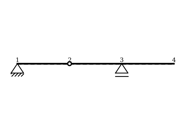
This example demonstrates how sStatics recognizes and reports an unstable structural system. A beam-like structure is modeled with insufficient constraints, creating a mechanism. The calculation is attempted using first-order structural analysis, and the system checks whether the stiffness matrix is regular (i.e., invertible).
This example illustrates:
Defining a structural system with bars, materials, and cross-sections
Applying supports and hinge conditions
Detecting insufficient constraints (loss of stiffness rank)
Querying whether the system is solvable or unstable
Visualizing the structural configuration
The example shows how sStatics automatically identifies instability. You can find the example as an executable Python file here.
Define the Structural System#
In this section, the static system is modeled. For a detailed step-by-step workflow, refer to the “Getting Started” example.
[1]:
# 1. Import required modules
from sstatics.core.preprocessing import (
    Node, Bar, Material, CrossSection, System
)
from sstatics.core.calc_methods import FirstOrder
from sstatics.core.postprocessing.graphic_objects import ObjectRenderer, SystemGeo

# 2. Define cross-section and material
cs = CrossSection(
    mom_of_int=2769,
    area=76.84,
    height=20,
    width=10,
    shear_cor=0.1
)
mat = Material(
    young_mod=21000,    # Young's modulus
    poisson=0.1,
    shear_mod=8100,
    therm_exp_coeff=0.1
)

# 3. Define nodes (supports intentionally insufficient)
node_1 = Node(0, 0, u='fixed', w='fixed')
node_2 = Node(200, 0)
node_3 = Node(400, 0, w='fixed')
node_4 = Node(600, 0)

# 4. Define bars with one hinge, producing a mechanism
bar_1 = Bar(node_1, node_2, cs, mat, hinge_phi_j=True)
bar_2 = Bar(node_2, node_3, cs, mat)
bar_3 = Bar(node_3, node_4, cs, mat)

bars = [bar_1, bar_2, bar_3]

# 5. Build the system
system = System(bars=bars)

# Show system graphic
ObjectRenderer(SystemGeo(system), 'mpl').show(show_axis=False)
Check if the System is Solvable#
A system is considered solvable if it is stable. If the stiffness matrix of the system is singular, the system is unstable.
To verify stability, we use the method solvable.
If the system is stable, the method returns
True.If the system is unstable, the method returns
False.
[2]:
# 6. Attempt structural analysis
solution = FirstOrder(system=system)

# 7. Check system stability
# solution.solvable → True if stiffness matrix is invertible, False otherwise
print("System solvable:", solution.solvable)
System solvable: False
In this example, the stiffness matrix is singular, and the terminal prints a corresponding warning. The method therefore returns False, indicating that the system is not solvable because it is unstable. Dadurch können nun keine Ergebnisgrößen, wie beispielsweise die Knotenverformungen oder Schnittkräfte erhalten werden.
Check if the System is Solvable#
To verify stability, we use the method solvable.
If the system is stable, the method returns
True.If the system is unstable, the method returns
False.
[3]:
# Perform calculation
solution = FirstOrder(system=system)

# Check whether the system is solvable (stable) or not
print(solution.solvable)
False
In this example, the stiffness matrix is singular, and the terminal prints a corresponding warning. The method therefore returns False, indicating that the system is not solvable because it is unstable.
In the example “PolePlan”, we will create a PolePlan object from the System object and visualize both the pole plan and the displacement figure.