
Cross-Section: IPE-80#
The following example demonstrates how a cross-section object can be created from a combination of polygons.
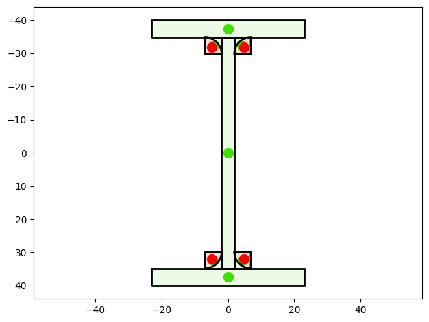
This example constructs an IPE-like I-section using:
simple polygons for flanges and web,
four square filler blocks (positive polygons) placed at the web–flange intersections,
four quarter-circle cutouts (negative CircularSector objects) to create realistic rounded fillets (radius r).
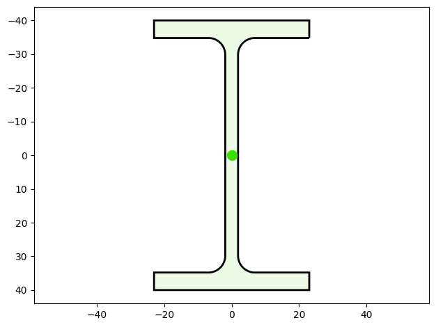
This combination reproduces a rounded I-profile despite polygon geometry constraints.
The cross-section is visualized and basic geometric properties are printed.
Parameters (units arbitrary):
height = 80
width = 46
web thickness = 3.8
flange thickness = 5.2
fillet radius = 5
Finally, the cross-section is visualized.
You can find the example as an executable Python file here.
Import Modules#
We start by importing the required classes for defining and visualizing the cross-section.
[1]:
import numpy as np
from sstatics.core.preprocessing.geometry import Polygon, CircularSector
from sstatics.core.preprocessing import CrossSection
from sstatics.core.postprocessing.graphic_objects import CrossSectionGeo, ObjectRenderer
Create Geometry#
First, we define the parameter that describe the geometry:
[2]:
# Parameters
height = 80.0
width = 46.0
tw = 3.8    # web thickness
tf = 5.2    # flange thickness
r = 5.0    # rounding radius

# Half-dimensions, center at (0,0)
h2 = height / 2.0
b2 = width / 2.0
Create Polygons#
Second, we define the polygons that discribe the geometry:
[3]:
# 1. Base polygons: flanges and web
# Top flange
top_flange = Polygon([
    (-b2, h2), (b2, h2),
    (b2, h2 - tf), (-b2, h2 - tf),
    (-b2, h2)
])

# Bottom flange
bottom_flange = Polygon([
    (-b2, -h2 + tf), (b2, -h2 + tf),
    (b2, -h2), (-b2, -h2),
    (-b2, -h2 + tf)
])

# Web (centered)
web = Polygon([
    (-tw/2.0, -h2 + tf), (tw/2.0, -h2 + tf),
    (tw/2.0,  h2 - tf), (-tw/2.0,  h2 - tf),
    (-tw/2.0, -h2 + tf)
])

# 2. Square filler blocks (positive)
# These squares fill the corner region before rounding is cut out.
# They ensure that subtracting the circular sectors creates correct fillets.

sq_tr = Polygon([
    (tw/2.0, h2 - tf),
    (tw/2.0 + r, h2 - tf),
    (tw/2.0 + r, h2 - tf - r),
    (tw/2.0, h2 - tf - r),
    (tw/2.0, h2 - tf)
])

sq_tl = Polygon([
    (-tw/2.0, h2 - tf),
    (-tw/2.0 - r, h2 - tf),
    (-tw/2.0 - r, h2 - tf - r),
    (-tw/2.0, h2 - tf - r),
    (-tw/2.0, h2 - tf)
])

sq_bl = Polygon([
    (-tw/2.0, -h2 + tf),
    (-tw/2.0 - r, -h2 + tf),
    (-tw/2.0 - r, -h2 + tf + r),
    (-tw/2.0, -h2 + tf + r),
    (-tw/2.0, -h2 + tf)
])

sq_br = Polygon([
    (tw/2.0, -h2 + tf),
    (tw/2.0 + r, -h2 + tf),
    (tw/2.0 + r, -h2 + tf + r),
    (tw/2.0, -h2 + tf + r),
    (tw/2.0, -h2 + tf)
])

fillet_blocks = [sq_tr, sq_tl, sq_bl, sq_br]
Create Circular Sectors#
Third, we create the circular sectors that discribes the negative cutouts
[4]:
# 3. Circular fillets (negative cutouts)
# These create the real rounding by *removing* quarter-circle regions.

ctr_tr = (tw/2.0 + r, h2 - tf - r)
ctr_tl = (-tw/2.0 - r, h2 - tf - r)
ctr_bl = (-tw/2.0 - r, -h2 + tf + r)
ctr_br = (tw/2.0 + r, -h2 + tf + r)

outer_arcs = [
    CircularSector(center=ctr_bl, radius=r, angle=np.pi/2,
                   start_angle=-np.pi/2, positive=False),
    CircularSector(center=ctr_br, radius=r, angle=np.pi/2,
                   start_angle=np.pi, positive=False),
    CircularSector(center=ctr_tr, radius=r, angle=np.pi/2,
                   start_angle=np.pi/2, positive=False),
    CircularSector(center=ctr_tl, radius=r, angle=np.pi/2,
                   start_angle=0.0, positive=False)
]
Create Cross-Section#
After defining the polygons and circular sectors that describe the geometry, we combine them into a single cross-section using the CrossSection class.
The geometry parameter takes a list of Polygon and CircularSector objects. Each object can either add material (default, positive=True) or subtract material (positive=False) to form cut-outs. By combining the outer boundary and the subtraction polygons, we create the characteristic shape of an I- or H-section.
This step results in a complete CrossSection object, which currently stores the geometric definition of the section. From this object, mechanical cross-section properties (such as area, centroid, and moments of inertia) can be calculated for further structural analysis.
[5]:
# 4. Build final cross-section
geometry = [top_flange, bottom_flange, web] + fillet_blocks + outer_arcs
cs = CrossSection(geometry=geometry)
Visualize Cross-Section#
The generated cross-section can then be visualized using the CrossSectionGraphic class.
By default, the merged parameter controls whether individual polygons are displayed separately or combined into a single geometry:
merged=Falsedisplays the individual objects separately.merged=Truecombines all objects and displays the overall cross-section as a single shape.
[6]:
# Visualize the geometry-object that create the cross-section
ObjectRenderer(CrossSectionGeo(cross_section=cs, merged=False), 'mpl').show()
[7]:
# Visualize the cross-section
ObjectRenderer(CrossSectionGeo(cross_section=cs), 'mpl').show()
Calculate cross-section properties#
[8]:
# 6. Extract geometric properties
A = cs.area
y_s = cs.center_of_mass_y
z_s = cs.center_of_mass_z
Iy = cs.mom_of_int
width_cs = cs.width
height_cs = cs.height
(yb, zb) = cs.boundary()
y_bottom, y_top = yb[0], yb[1]
z_top, z_bottom = zb[0], zb[1]

print("=== IPE-like Cross-Section (rounded, approx.) ===")
print(f"Given dims: height={height}, width={width}, tw={tw}, tf={tf}, r={r}")
print(f"Area A                     : {A:.4f}")
print(f"Centroid y_s, z_s         : ({y_s:.4f}, {z_s:.4f})")
print(f"Moment of inertia Iy      : {Iy:.4f}")
print(f"Width, Height             : {width_cs:.4f}, {height_cs:.4f}")
print(f"Boundary in y-direction   : bottom = {y_bottom:.4f},"
      f" top = {y_top:.4f}")
print(f"Boundary in z-direction   : top = {z_top:.4f},"
      f" bottom = {z_bottom:.4f}")
=== IPE-like Cross-Section (rounded, approx.) ===
Given dims: height=80.0, width=46.0, tw=3.8, tf=5.2, r=5.0
Area A                     : 764.3418
Centroid y_s, z_s         : (0.0000, 0.0000)
Moment of inertia Iy      : 801378.4533
Width, Height             : 46.0000, 80.0000
Boundary in y-direction   : bottom = -23.0000, top = 23.0000
Boundary in z-direction   : top = -40.0000, bottom = 40.0000